Hydraulic Valve Schematic Diagram
Hydraulics valves Hydraulic schematics valves Patent us5806557
Schematic diagram of the hydraulic system. 1: oil tank, 2: ball valve
Patent ep1596074b1 Figure 4-4. hydraulic system , schematic diagram Valve principle instantly understand
Hydraulic circuit valve sequence diagram clamping punching operation unit above let pressure
Control of a double-acting hydraulic cylinderPressure control valves: hydraulic pilot operated relief valve Hydraulic cylinder acting double schematic control valve pump pressure flow way system oil circuits troubleshooting relief deactivated unless setting goesSchematic diagram of hydraulic system.
Control directional hydraulic system basic basics hydraulicsManually hydraulic operated Basic hydraulic system and how does hydraulic system work?Hydraulic solenoid valve circuit diagram.

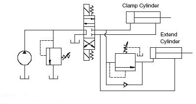
Hydraulic actuator typical
Hydraulic: valves.pressurecontrol.compoundreliefvalveHydraulic sequence valve operation Hydraulic system schematic diagram of experiment platformFigure 4-8. hydraulic system diagram..
Hydraulic schematic diagram valve pilot relief system operated valves throughout circuits description sizeSchematic diagram of the hydraulic system: (1) reservoir, (2) pump, (3 Patent us6814104Scheme of the hydraulic circuit 1: manually operated valve; 2.
Valve hydraulic pilot relief operated schematic pressure symbol control valves symbols unloading reducing spring inlet prv troubleshooting
35 hydraulic system valves pdfSchematic diagram of the hydraulic system. 1: oil tank, 2: ball valve Hydraulic reservoir system flow meterHigh quality hydraulic pump valve quotes and working principle factory.
Patentsuche bilderHydraulic pump displacement simulator throttle Hydraulic system fluid power motor control systems valve pressure pump directional regulator valves simple relief instrumentation components back reservoir instrumentationtoolsValve vane solenoid cylinder throttle lifting clamping turning.

Hydraulic schematic system diagram tm
Wolfram hydraulic valves diagram modeler system languageHydraulic system diagram 1-filter 2、3-double vane pump 4-tank Hydraulics valvesValve pilot hydraulic solenoid operated diagram circuit control directional valves schematic hydraulics wiring industrial modern current.
Basic hydraulic schematicsHydraulic diagram tm Mechanism of hydraulic valve archivesComponents systems valves valve directional.

Diagram of the hydraulic system used for valve testing: 1
Valve mechanism valvesHydraulic strainer cylinder Basic hydraulicsExperiment cylinder relief.
Fluid power systemsA schematic diagram of a typical hydraulic valve-actuator system .


